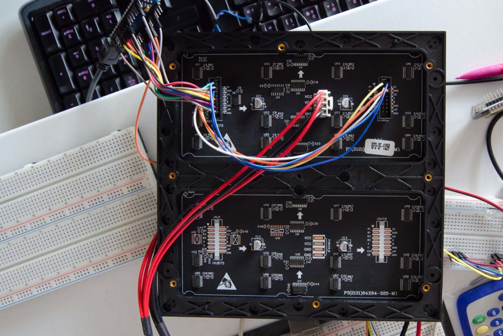
Dans la partie 1, nous avons vu que pour remplir les registres à décalage, il y avait 6 broches de données (R1, G1, B1 et R2, G2, B2) synchronisée par une broche d’horloge… un peu comme un port SPI avec 6 MOSI. D’où l’idée d’utiliser le port SPI hardware de l’Arduino pour envoyer les données. Oui mais… il n’y a qu’un seul MOSI. Mais dans la matrice c’est un registre à décalage… et on peut mettre plusieurs matrices de LED en série pour les chaîner. Et si on chaînait une matrice avec elle même ? Ça pourrait faire une seule broche de donnée + l’horloge… donc MOSI et SCK.
Bon, c’est pas très net cette histoire. Avec un schéma ça sera plus simple.
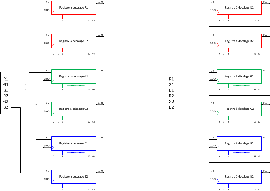
À gauche, le schéma simplifié de la partie 1. On envoie en 64 fois en série (pour les 64 LED de large) R1, G1, B1 et R2, G2, B2 en parallèle.
À droite, le schéma de cette partie. On a chaîné les registres à décalage entre eux. On envoie cette fois 384 données en série sur le premier registre, quand il sera plein il commencera à pousser au suivant et ainsi de suite jusqu’à remplir le dernier registre bleu. Vu que tout est décalé à chaque coup d’horloge, on transmet le dernier pixel bleu B2 en premier pour finir par le premier rouge R1.
Vu que les registres à décalage des différentes couleurs de la même matrice sont mis en série, ça fait un gros registre à décalage de la forme R1-R2-G1-G2-B1-B2. Il va falloir pousser en premier les pixels bleus de la ligne 2, puis les bleus de la ligne 1, puis les verts de la ligne 2….
#include <FastGPIO.h>
#include <SPI.h>
#include <stdint.h>

static const uint8_t PIN_A = A0;   // A
static const uint8_t PIN_B = A1;   // B
static const uint8_t PIN_C = A2;   // C
static const uint8_t PIN_D = A3;   // D
static const uint8_t PIN_E = A4;   // D

static const uint8_t PIN_LAT = 6;  // LAT
static const uint8_t PIN_OE  = 7;  // OE

static uint8_t displayLineIndex = 31;
static uint8_t dataLineIndex = 0;

static unsigned char bus1_bits[] = {
 0x00, 0x00, 0x00, 0x00, 0x00, 0x00, 0x00, 0x00, 0x00, 0x00, 0x00, 0x00,
 0x00, 0x00, 0x00, 0x00, 0x00, 0x00, 0x00, 0x00, 0x00, 0xe0, 0x81, 0x03,
 0x00, 0x00, 0x00, 0x00, 0x00, 0xe0, 0xff, 0x07, 0x00, 0x00, 0x00, 0x00,
 0x00, 0xf0, 0xff, 0x0f, 0x00, 0x00, 0x00, 0x00, 0x00, 0x30, 0xff, 0x0c,
 0x00, 0x00, 0x00, 0x00, 0x00, 0xf0, 0xff, 0x0f, 0x00, 0x00, 0x00, 0x00,
 0x00, 0xf0, 0xff, 0x0f, 0x00, 0x00, 0x00, 0x00, 0x00, 0x30, 0x00, 0x0e,
 0x00, 0x00, 0x00, 0x00, 0x00, 0x30, 0x00, 0x0c, 0x00, 0x00, 0x00, 0x00,
 0x00, 0x30, 0x00, 0x0c, 0x00, 0x00, 0x00, 0x00, 0x00, 0x38, 0x00, 0x1c,
 0x00, 0x00, 0x00, 0x00, 0x00, 0x38, 0x00, 0x1c, 0x00, 0x00, 0x00, 0x00,
 0x00, 0x38, 0x00, 0x1c, 0x00, 0x00, 0x00, 0x00, 0x00, 0x38, 0x00, 0x1e,
 0x00, 0x00, 0x00, 0x00, 0x00, 0xf0, 0xff, 0x0f, 0x00, 0x00, 0x00, 0x00,
 0x00, 0x30, 0x00, 0x0e, 0x00, 0x00, 0x00, 0x00, 0x00, 0xf0, 0xff, 0x0f,
 0x00, 0x00, 0x00, 0x00, 0x00, 0xf0, 0xff, 0x0f, 0x00, 0x00, 0x00, 0x00,
 0x00, 0x00, 0x00, 0x00, 0x00, 0x00, 0x00, 0x00, 0x00, 0x00, 0x00, 0x00,
 0x00, 0x00, 0x00, 0x00, 0x00, 0x00, 0x00, 0x00, 0x00, 0x00, 0x00, 0x00,
 0x00, 0x00, 0x00, 0x00, 0x00, 0x00, 0x00, 0x00, 0x00, 0xe0, 0x81, 0x03,
 0x00, 0x00, 0x00, 0x00, 0x00, 0xe0, 0xff, 0x07, 0x00, 0x00, 0x00, 0x00,
 0x00, 0xf0, 0xff, 0x0f, 0x00, 0x00, 0x00, 0x00, 0x00, 0x30, 0xff, 0x0c,
 0x7c, 0x74, 0x3c, 0x78, 0x1e, 0xf0, 0xff, 0x0f, 0xc0, 0xcc, 0x60, 0x44,
 0x26, 0xf0, 0xff, 0x0f, 0x80, 0x84, 0x40, 0x42, 0x22, 0x30, 0x00, 0x0e,
 0xfc, 0x84, 0x40, 0x42, 0x1e, 0x30, 0x00, 0x0c, 0x84, 0x84, 0x40, 0x42,
 0x02, 0x30, 0x00, 0x0c, 0xcc, 0x44, 0x20, 0x66, 0x12, 0x38, 0x00, 0x1c,
 0x78, 0x3c, 0x3c, 0x5c, 0x0c, 0x38, 0x00, 0x1c, 0x00, 0x04, 0x00, 0x40,
 0x00, 0x38, 0x00, 0x1c, 0x00, 0x04, 0x00, 0x40, 0x00, 0x38, 0x00, 0x1e,
 0x00, 0x04, 0x00, 0x40, 0x00, 0xf0, 0xff, 0x0f, 0x00, 0x00, 0x00, 0x00,
 0x00, 0x30, 0x00, 0x0e, 0x00, 0x00, 0x00, 0x00, 0x00, 0xf0, 0xff, 0x0f,
 0x00, 0x00, 0x00, 0x00, 0x00, 0xf0, 0xff, 0x0f, 0x00, 0x00, 0x00, 0x00,
 0x00, 0x00, 0x00, 0x00, 0x00, 0x00, 0x00, 0x00, 0x00, 0x00, 0x00, 0x00,
 0x00, 0x00, 0x00, 0x00, 0x00, 0x00, 0xff, 0x07, 0x00, 0x00, 0x00, 0x00,
 0x00, 0xc0, 0xff, 0x0f, 0x00, 0x00, 0x00, 0x00, 0x00, 0xc0, 0xff, 0x0f,
 0x00, 0x00, 0x00, 0x00, 0x00, 0xc0, 0xff, 0x0f, 0x00, 0x00, 0x00, 0x00,
 0x00, 0xc0, 0xff, 0x0f, 0x00, 0x00, 0x00, 0x00, 0x00, 0xc0, 0xff, 0x0f,
 0xf0, 0x10, 0x78, 0x7e, 0x1f, 0xc0, 0xff, 0x0f, 0x18, 0x10, 0x04, 0x30,
 0x04, 0xc0, 0x01, 0x0e, 0x08, 0xfc, 0x05, 0x18, 0x04, 0xc0, 0x01, 0x0e,
 0x08, 0x10, 0x05, 0x0c, 0x04, 0xc0, 0x01, 0x0e, 0xf0, 0x90, 0x38, 0x04,
 0x04, 0xc0, 0x01, 0x0e, 0x80, 0xd0, 0x04, 0x02, 0x04, 0xc0, 0x01, 0x0e,
 0x80, 0x50, 0x04, 0x02, 0x14, 0xc0, 0x01, 0x0e, 0x80, 0x30, 0x04, 0x42,
 0x0c, 0xc0, 0x01, 0x0e, 0xf8, 0x30, 0x78, 0x3c, 0x04, 0xc0, 0xff, 0x0f,
 0x00, 0x00, 0x00, 0x00, 0x00, 0xc0, 0x01, 0x0e, 0x00, 0x00, 0x00, 0x00,
 0x00, 0xc0, 0xff, 0x0f, 0x00, 0x00, 0x00, 0x00, 0x00, 0xc0, 0xff, 0x0f,
 0x00, 0x00, 0x00, 0x00, 0x00, 0x80, 0xff, 0x07, 0x00, 0x00, 0x00, 0x00,
 0x00, 0x00, 0x00, 0x00, 0x00, 0x00, 0x00, 0x00, 0x00, 0x00, 0x00, 0x00,
 0x00, 0x00, 0x00, 0x00, 0x00, 0x00, 0x00, 0x00 } ;

SPISettings settingsA(8000000, LSBFIRST, SPI_MODE0);

void setup() {
  // Initialisation
  SPI.begin();

  FastGPIO::Pin<PIN_A>::setOutput(LOW);
  FastGPIO::Pin<PIN_B>::setOutput(LOW);
  FastGPIO::Pin<PIN_C>::setOutput(LOW);
  FastGPIO::Pin<PIN_D>::setOutput(LOW);
  FastGPIO::Pin<PIN_E>::setOutput(LOW);

  FastGPIO::Pin<PIN_LAT>::setOutput(LOW);
  FastGPIO::Pin<PIN_OE>::setOutput(HIGH);

  //Debug
  FastGPIO::Pin<4>::setOutput(LOW);

}

void loop() {
   refreshDisplay();
}

void refreshDisplay() {

  //Set the address of the line to display
  (displayLineIndex & 1) ? FastGPIO::Pin<PIN_A>::setOutputValueHigh() : FastGPIO::Pin<PIN_A>::setOutputValueLow();
  (displayLineIndex & 2) ? FastGPIO::Pin<PIN_B>::setOutputValueHigh() : FastGPIO::Pin<PIN_B>::setOutputValueLow();
  (displayLineIndex & 4) ? FastGPIO::Pin<PIN_C>::setOutputValueHigh() : FastGPIO::Pin<PIN_C>::setOutputValueLow();
  (displayLineIndex & 8) ? FastGPIO::Pin<PIN_D>::setOutputValueHigh() : FastGPIO::Pin<PIN_D>::setOutputValueLow();
  (displayLineIndex & 16) ? FastGPIO::Pin<PIN_E>::setOutputValueHigh() : FastGPIO::Pin<PIN_E>::setOutputValueLow();

  //Lock register
  FastGPIO::Pin<PIN_LAT>::setOutputValueLow();

  //Activate display
  FastGPIO::Pin<PIN_OE>::setOutputValueLow();

  //Oscillo debug
  FastGPIO::Pin<4>::setOutputValueHigh();

  //We can send data for the next line to display...
  SPI.beginTransaction(settingsA);
  for (uint8_t iByte = 0; iByte < 8; ++iByte) {
    SPI.transfer(bus1_bits[(dataLineIndex+32)*8 + iByte]);
  }

  for (uint8_t iByte = 0; iByte < 8; ++iByte) {
    SPI.transfer(bus1_bits[(dataLineIndex)*8 + iByte]);
  }

  for (uint8_t iByte = 0; iByte < 16; ++iByte) {
    SPI.transfer(0);
  }

  for (uint8_t iByte = 0; iByte < 16; ++iByte) {
    SPI.transfer(0);
  }

  SPI.endTransaction();

   //Desactivate display
   FastGPIO::Pin<PIN_OE>::setOutputValueHigh();

   //Oscillo debug
   FastGPIO::Pin<4>::setOutputValueLow();

   //Latch
   FastGPIO::Pin<PIN_LAT>::setOutputValueHigh();


  if (++displayLineIndex == 32) {
    displayLineIndex = 0;
  }

  if (++dataLineIndex == 32) {
    dataLineIndex = 0;
  }
}

